Effect of electron dose rate on the total dose tolerance limit in ZIF-8 metal-organic-framework (MOF)
- Abstract number
- 325
- Presentation Form
- Poster
- DOI
- 10.22443/rms.mmc2023.325
- Corresponding Email
- [email protected]
- Session
- Poster Session Two
- Authors
- Pritam Banerjee (1), Kathrin L. Kollmannsberger (2), Roland A. Fischer (2), Joerg R. Jinschek (1)
- Affiliations
-
1. National Centre for Nano Fabrication and Characterisation (DTU Nanolab), Technical University of Denmark
2. TUM School of Natural Sciences, Department of Chemistry, Technical University of Munich
- Keywords
MOF, ZIF-8, Electron microscopy, Diffraction and Electron dose
- Abstract text
Zeolitic imidazolate frameworks-8 (ZIF-8) are a sub-class of metal-organic-frameworks (MOF), hierarchically porous materials, where in ZIF-8 zinc (Zn) atoms are linked to 2-methylimidazolate linkers. ZIF-8 has a cubic crystal structure (space group I43m, lattice parameter = 16.99Å) [1] . This chemically stable crystalline structure with large pores of 11.6Å is well suited for the adsorption of both guest aggregates and gas molecules [1][2]. This ability opens a wide field of application, including catalysis as well as gas storage and separation. However, this also depends on our ability to characterize such potentially complex structures with atom-level accuracy [3].
In general, high-resolution scanning and transmission electron microscopy (HR-S/TEM) exhibits such capability, but by using high-energy electrons. Using an electron beam as a probe when assessing the structure of beam-sensitive and soft matter, can be invasive [4]. Therefore, we need to investigate and understand when and how the studied original structure might be altered unintentionally in these atomic-scale experiments. This knowledge will give us control over all electron-sample interactions in our experiment and allows us to minimize (or at least mitigate) unintended structural changes.
Here, we study the stability of ZIF-8 in HR-S/TEM atomic scale imaging experiments, specifically the critical total electron dose tolerated. In the literature [3][5][6], values of total dose are reported, however not all affecting parameters have been considered.
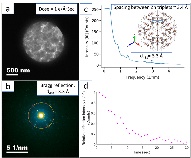
One method of assessing structural changes in a crystalline sample, e.g. caused by exposure to high-energy electrons, is by quantifying the drop in the intensity of specific Bragg spots in electron diffraction (ED) pattern. Here, we have examined the dose-rate dependence of the stability of ZIF-8 MOF nanoparticles (average size ~ 160 nm) with varying dose rate of 0.1, 1 and 6.6 e- A-2 s-1, respectively. Time series of ED pattern have been recorded in FEI Tecnai G2 microscope (LaB6, 200 keV) with exposure time of 1 sec until all the Bragg diffraction spots have completely faded out. The bright field TEM image of the ZIF-8 nanoparticles and the corresponding ED pattern, taken with a dose rate of 1 e- A-2 s-1, are shown in fig. 1a and 1b, respectively. The radial average of the intensity of the Bragg rings (shown in fig. 1b) are plotted in fig. 1c. The time dependence of the relative intensity of the {431} Bragg spot, corresponding to an interplanar spacing of 3.3 Å between Zn triplets in the unit cell along [111] direction and an indication of resolving these Zn triplets in the HR-S/TEM imaging, is plotted in fig. 1d. We use this approach to estimate the effect of dose-rate on the critical dose tolerance limit in our ZIF-8 material.
Figure. 1(a) Bright field image of ZIF-8 MOF nanoparticles taken with an electron dose rate of 1 e- A-2 s-1. (b) Ring diffraction pattern showing the {431} Bragg reflection at t =1sec (first acquisition). (c) Radial average of the Bragg reflections. Inset showing schematic of ZIF-8 unit cell along [111] direction. (d) Relative intensity plot of {431} Bragg reflection with time (I0 = intensity at t = 1sec, I = intensity at t sec).
Acknowledgement:
The authors acknowledge funding from the Novo Nordisk Foundation. Project: Electron Microscopy of Dynamical Processes (NNF21OC0072844)
- References
[1] M. Bergaoui, M. Khalfaoui, A. Awadallah-F, and S. Al-Muhtaseb, “A review of the features and applications of ZIF-8 and its derivatives for separating CO2 and isomers of C3- and C4- hydrocarbons,” J. Nat. Gas Sci. Eng., vol. 96, p. 104289, Dec. 2021, doi: 10.1016/j.jngse.2021.104289.
[2] K. L. Kollmannsberger, L. Kronthaler, J. R. Jinschek, and R. A. Fischer, “Defined metal atom aggregates precisely incorporated into metal–organic frameworks,” Chem. Soc. Rev., 2022, doi: 10.1039/D1CS00992C.
[3] Y. Zhu et al., “Unravelling surface and interfacial structures of a metal–organic framework by transmission electron microscopy,” Nat. Mater., vol. 16, no. 5, pp. 532–536, May 2017, doi: 10.1038/nmat4852.
[4] R. F. Egerton, “Radiation damage to organic and inorganic specimens in the TEM,” Micron, vol. 119, no. November 2018, pp. 72–87, Apr. 2019, doi: 10.1016/j.micron.2019.01.005.
[5] S. Ghosh, P. Kumar, S. Conrad, M. Tsapatsis, and K. A. Mkhoyan, “Electron-Beam-Damage in Metal Organic Frameworks in the TEM,” Microsc. Microanal., vol. 25, no. S2, pp. 1704–1705, 2019, doi: 10.1017/s1431927619009255.
[6] S. Ghosh, H. Yun, P. Kumar, S. Conrad, M. Tsapatsis, and K. A. Mkhoyan, “Two Distinct Stages of Structural Modification of ZIF-L MOF under Electron-Beam Irradiation,” Chem. Mater., vol. 33, no. 14, pp. 5681–5689, 2021, doi: 10.1021/acs.chemmater.1c01332.